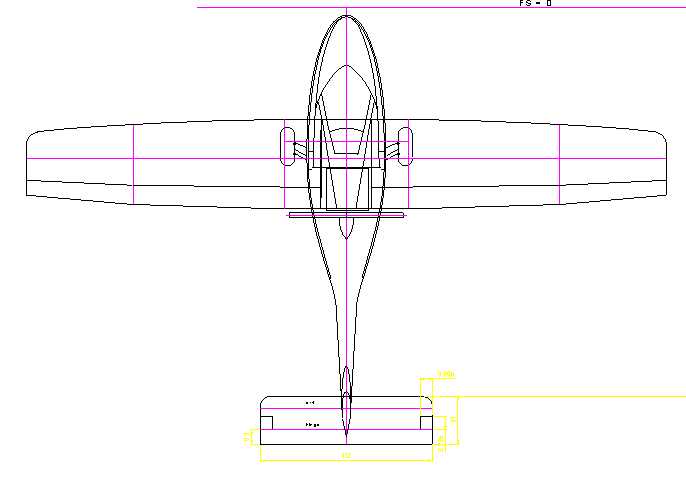
These are some examples of what I have worked on in the past.
Bye Aerospace StratoAir Net First Flight and eFlyer Flight Tests (2018)
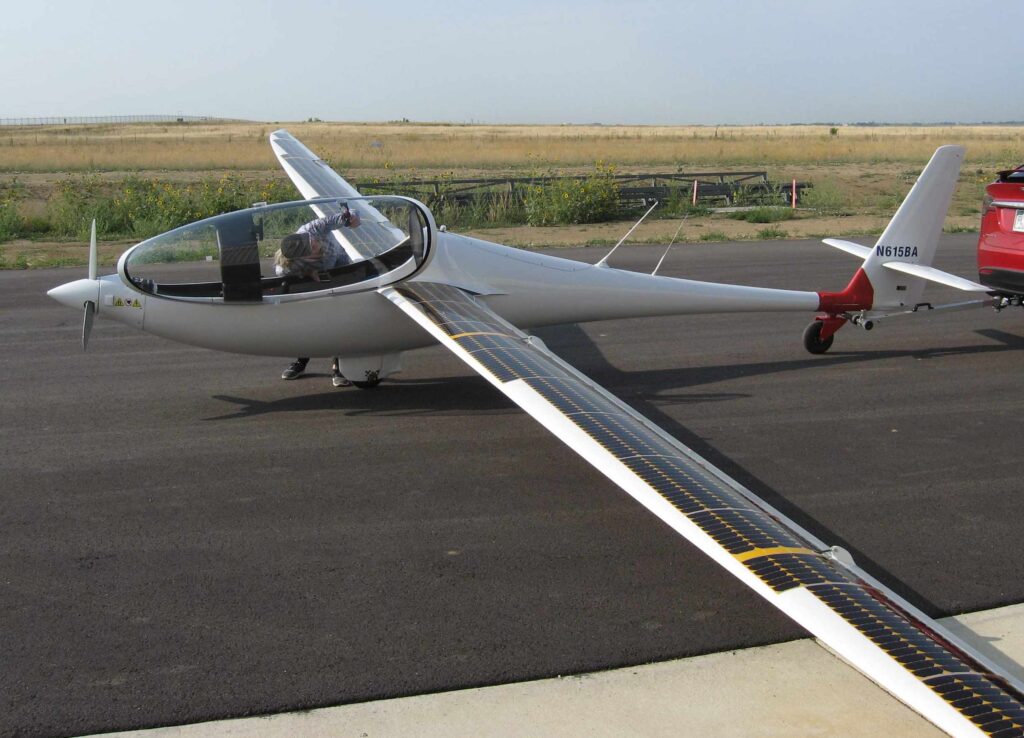
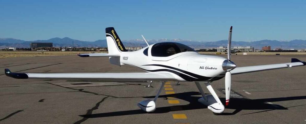
SAN is a new electric motorglider based on the Duckhawk which was modified with an electric motor in the nose and batteries aft of the cockpit. It has solar panels on the wing upper surfaces. I performed the first flight and evaluated different propellers for performance. I also performed a number of test flights in the eFlyer for Bye Aerospace in Colorado.
Test Flying the Flight Design F2 (2018-19)
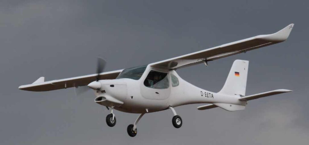
The F2 is a completely new composite LSA two-seater powered by a fuel-injected Rotax engine. It was designed to be spin resistant. I performed the first flights of the two F2 prototypes and took the second one through the full engineering and certification flight tests for ASTM requirements. This took place in the Czech republic.
Test Flying the South Korean KLA-100 (2018)

The KLA-100 is a new Light Sport Airplane developed by the South Koreans and the German company Flight Design. It is powered by a 100 hp Rotax 912 iSc. I performed a number of development and certification test flights with this airplane at the Goheung Aviation Research Center, among them spin resistance and flutter. The airplane handled very well and thanks to its large canopy, has exceptional visibility. It has been a pleasure to work with the very capable Korean test team on this project.
Red Bull Air Race Team Muroya (2017-2019)

I was providing engineering support for Yoshi Muroya’s Red Bull Air Race Team in preparation for the Air Races by developing tools to quickly analyze flight data to evaluate and improve engine cooling and performance. I was using these programs to monitor performance and engine setup during the races as well as for test flights with modifications. This helped us win many races and one world championship.
Nighthawk (2016-2020)

The Nighthawk is a new design for the purpose of quiet surveillance. The all-composite airframe seats three people in tandem. Its primary powerplant will be a SMA SA-305 Diesel engine. With a 57 ft wingspan, it resembles a motorglider. I am providing engineering support, mainly structural analysis and flight test planning, as part of a team of companies which are designing and building this unique aircraft. It made its successful first flight on December 29, 2020.
New Pulsar First Flight (2016)

I inspected this Pulsar III and performed the successful first flight for the proud builders Lance and Jerry. It is equipped with a Rotax 912iS engine. It is the first Pulsar III with this engine.
Rotary Engine Powered Harmon Rocket (2013-2015)

Russ MacFarlane started the rotary engine project as a showcase to the performance of these engines with the goal to set a world time-to-climb to 10,000 ft record with me as the project engineer. The late Jim Mederer of Racing Beat, developed the custom 600 hp twin-rotor rotary engine and performed extensive testing on the test stand in his shop, integrating a turbocharger and a planetary gear box from a Bell 47 helicopter to reduce the 8500 engine rpm to 2900 prop rpm. Craig Catto designed the propeller to convert this power into thrust. Once the dyno work was complete, I found Dan Grey’s shop and decided that he would be suitable for combining the rotary engine with a Harmon Rocket airframe which we had purchased for the record attempt. It then took Dan three years to get the installation and airframe modifications to the point where he could make the record flight in 2018.
Engine Cooling Lancair Evolution with Piston Engine (2015)

Lancair installed a Lycoming YTEO-540 IE2 in an Evolution airframe. The new engine is a FADEC engine, twin turbocharged and intercooled. With it, the aircraft is capable of a similar flight envelope as the turbine powered version. I performed cooling tests and worked with Lancair on cooling improvements and drag reduction on the prototype cowling. Shown in the picture above is the final result.
Support for Team Chambliss (2015)
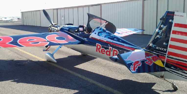
During the 2014/2015 winter break, I supported the efforts of Kirby’s Red Bull Air Race Team Chambliss in getting their Edge 540 V3 ready for the new race season in the areas of aerodynamics and powerplant.
AQUILA Engine Cooling Investigation (2014)
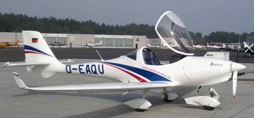
The Aquila is an all-composite two-seat VLA built in Germany, powered by a Rotax 912. I carried out a very complete investigation of the engine cooling system performance. This included the installation of test and data recording equipment. The engine temperatures and pressures were measured during several test flights in the baseline configuration and with a few modifications. After I analyzed the data, I was able make recommendations for improvements, especially for the planned installation of the turbocharged Rotax 914 which required improved cooling.
Lancair Evolution Low Hinge Moment Ailerons (2013)

To reduce the aileron stick forces on the short side side stick of the fast Lancair Evolution, aerodynamic modifications were developed and flight tested. New ailerons with improved control feel and effectiveness were installed and made available to the customers.
“Plane Driven” Roadable Sportsman (2010)
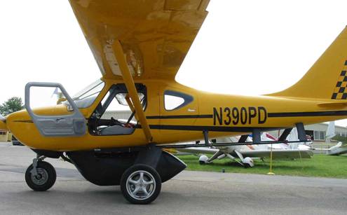
The plan was to create an airplane which, if the weather turned bad on a cross country, could be quickly converted to road mode so it could be driven on the road through the weather to the next airport and resume flying. The Sportsman was selected because of its folding wings and excellent load carrying capabilities. To accomplish this, I designed a number of modifications: a new nose gear with street legal tire, dual brakes and steering. A removable steering wheel and mechanism was connected to the nose gear. A new main gear, automotive brakes and suspension, driven by a separate engine attached to rails which allow the main gear and road engine to be moved from its normal position in flight to an aft position in road mode. The rail structure interfaced with the fuselage structure to transfer the gear loads into the fuselage. The tips of the horizontal tail had to be foldable to bring the width down to the maximum allowed on the street. The modifications were designed and built to proof-of-concept status in less than six months.
Engineering Test Pilot for Columbia Aircraft (2003 – 2009)
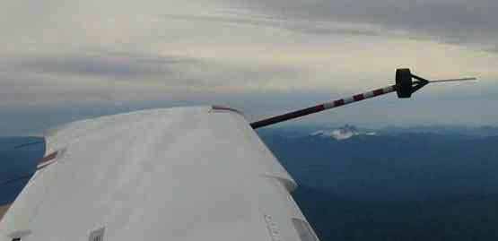
I tested numerous configurations and new systems on the Columbia 350 and 400. This involved first flights with modifications and developmental and certification tests as a DER test pilot. Examples are new avionics and software evaluations including synthetic vision, lots of stalls, spin resistance, engine and propeller operating characteristics at high altitude (FL250), level and climb performance, take off performance, noise tests, EMI tests, unusable fuel tests, engine and accessory function and cooling tests, static and dynamic stability and control, autopilot tests, new systems tests such as airconditioning and rudder hold, pitot and static system calibration and others.
Columbia 400 and TSIO-550C Engine Installation

I was involved from the beginning in the Columbia 400 project, which was derived from the normally aspirated Columbia 350. It was fitted with a twin-turbo-supercharged Continental TSIO-550-C. This involved designing a new induction system, cowling, baffling and fuel system changes for improved cooling for altitudes up to FL250. For positive control during landing the design of the elevator was changed, which allowed maintaining the very docile stall behavior of the Columbia 350. This involved many hours of design, performance and flight characteristics testing. The type certificate was received at Sun ‘n Fun 2004.
Design of Spin Recovery Features for the Columbia 400 (2004)
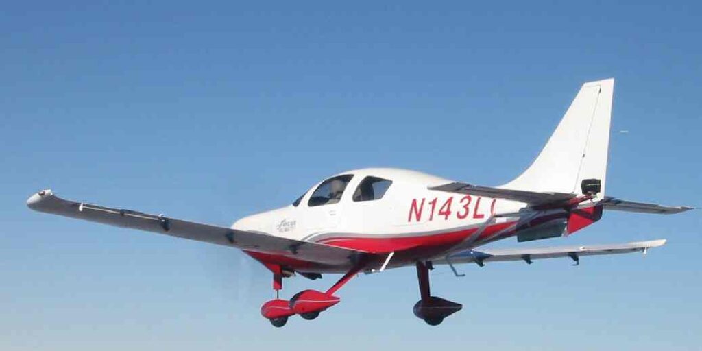
After testing the initial version of the Columbia 400 for spin resistance like the Columbia 350, it was decided to modify the airplane to make it spin-recoverable while trying to maintain the excellent stall characteristics of this airplane. Many designs to modify the tail were evaluated and flight tested for their spin recovery performance. At the same time, a reliable anti-spin chute system was developed and tested for the use on the Columbia 400. In its final configuration the airplane was recoverable from normal category spins at all weight and CG combinations at altitudes up to 25,000 ft.
Columbia FADEC Engine Installation and Testing (2002)

The addition of FADEC to an engine greatly increases the complexity of the system. The engine control units, sensor installation and wiring were custom-fitted to two Columbia airframes (350 and 400). The removal of the magnetos required the now “all-electric” engine to have redundant power sources and protection for EMI, HIRF and lightning strikes were necessary. Because the engine manufacturer had only performed testing on a test stand at sea level, all altitude performance testing was done in flight. Actual operational testing uncovered many small issues which were addressed by the engine manufacturer during a lengthy development program.
Pulsar Drag Reduction (2001)

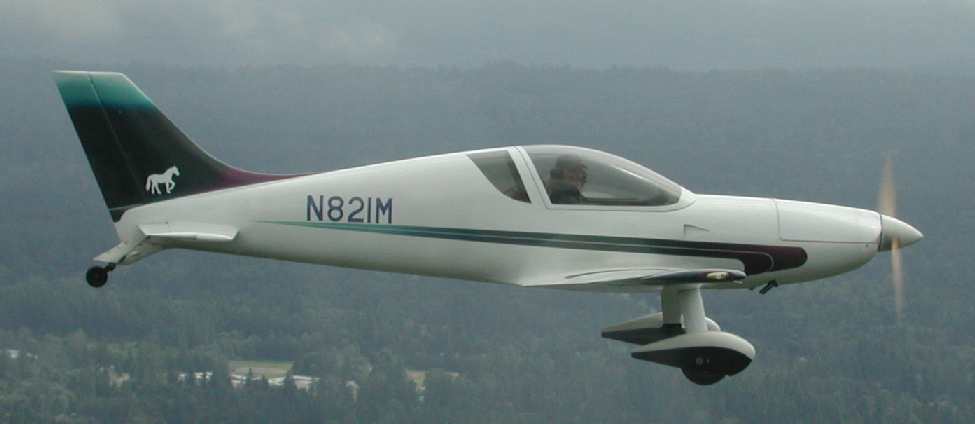
Before and After
I made a number of aerodynamic improvements and cleaned up the airframe of my Pulsar XP. The modifications included converting it from a nosegear to a tailwheel installation of my own design. The result was a 10 kts increase in cruise performance.
Adam A500 Front & Aft Engines (2001)

As the lead powerplant engineer at Adam Aircraft, I worked on the development of the first A500. It was powered by two twin-turbocharged, twin-intercooled 350 hp TCM TSIO-550 E engines. Hartzell provided the two three-bladed constant speed propellers. The cowlings were designed for optimum cooling and low drag, both engines have downdraft cooling. New engine mounts were designed, the induction system for both front and aft engine, which were newly created from the compressors upstream to the airfilter, were identical for front and aft engine to reduce parts count.
Adam A500 Tail & Boom Structural Design (2001)
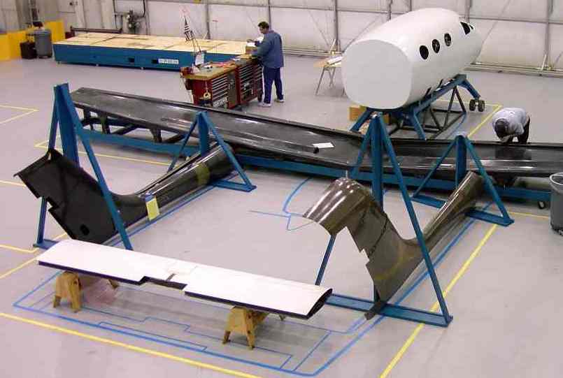
The A500 is an all-composite, centerline thrust twin-engined airplane. I developed preliminary loads for the twin-boom arrangement and designed the tail and boom structure, which consists of carbon fiber prepreg. The horizontal tail is a separate piece bolted to the two vertical stabilizers, which provides support for the full span elevator, with mass balance and trim tab. The boom attachment to the wings and the main gear attachment, which is part of the boom structure, posed a unique challenge. The load-carrying skin is stiffened by sandwich construction using Nomex honeycomb. Access panels allow assembly and inspection of the controls inside the structure, and special protection was added in the aft propeller plane from shedding ice. The first A500 made its successful first flight about six months after the first part was built.
Cessna C-337 Aft Engine Installation (1999)
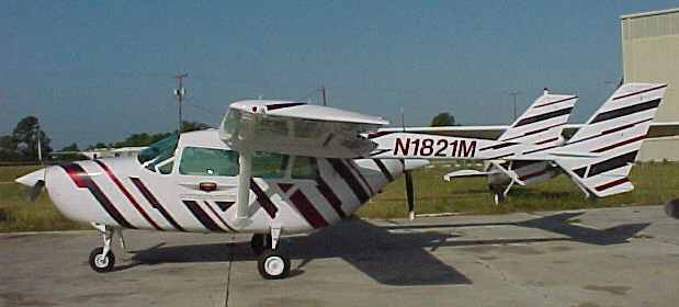
The Cessna Skymaster is a centerline thrust twin, with two 200 hp Continental engines. I developed a one-time engine installation for the aft engine, using a TCM IO-360 ES. To improve the aft engine cooling, I changed the original Cessna downdraft cooling to updraft cooling. Flight tests evaluated engine cooling and performance, it was found that the airplane’s performance was improved. It was also determined that most of the cooling air exited through the top louvers rather than the annular exit, which could have been eliminated.
TCM (GAP) Diesel Engine (1999)

Teledyne Continental Motors had developed an aircraft diesel engine under the NASA funded GAP program. After extensive tests on the test stand, I was asked to install the engine in their Cessna Skymaster front engine compartment for flight testing. The TCM diesel engine was a 200 hp direct drive, turbo-supercharged liquid cooled engine. For this installation, the airframe had to be modified to accommodate the different attachment locations of the engine. Locations for oil radiator, two coolant radiators and the induction system had to be found, and new cowlings were made. The airplane fuel system was modified to separate jet fuel in one wing from Avgas in the other wing for the conventional aft engine. Subsequently the engine was run and briefly flown, but to date no further testing has been done.
Mooney TCM IO-360 ES-Engine (1996)

Teledyne Continental Motors had come out with an improved version of their normally aspirated six-cylinder 210 hp engine, the IO-360 ES, which is also used in the Cirrus SR20. I developed the installation of this engine in Mooney M20F,J models, and obtained the STC with this engine as a replacement for the 200 hp four-cylinder Lycoming. In combination with a tuned induction system, tuned exhaust and low drag cowling, in which the cowl flaps were eliminated, the modified Mooney climbs better and is at least 10 kts faster than the unmodified version. The six cylinders provide smoother operation and better efficiency. In cooperation with Hartzell, a new propeller was developed and tested, which accounted for some of the performance increase.
Gross Weight Increase Certification Daetwyler MD-3 (1994)
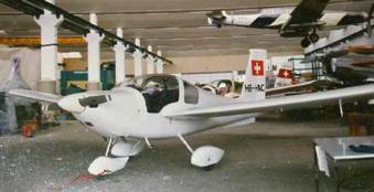
The MD-3 Swiss Trainer is an all-metal two-seat aerobatic airplane, which was developed in Switzerland. After initial certification, I was the lead engineer as the airplane went through a number of major modifications. Among them was a complete redesign of the wing spar, wing attachment to fuselage, fuselage height increase, canopy, exhaust and propeller changes, some of which were necessary for a gross weight increase. The engineering effort to accomplish this included structural analysis of components, structural tests, and flight tests. A partial spin test program was also required. The work was coordinated with the Swiss certification authorities and the FAA. Afterwards the whole project was sold to Malaysia, where I assisted in setting up production and training local workers.
Full Scale Wing Fatigue Test Daetwyler MD-3 (1993)
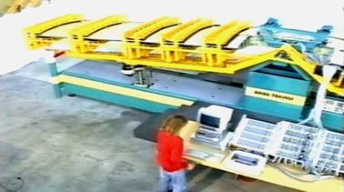
In order to determine the fatigue life of the MD-3, I supervised a full-scale wing test. The wing was mounted inverted on a test stand and subjected to the equivalent of millions of load cycles, including an aerobatic spectrum. Three lives of ten thousand hours each were simulated, while the stress in the structure was monitored constantly with strain gages. A computer controlled the amplitude and sequence of the load cycles, which ranged from –3g to +6g for this airplane. The forces from two electric actuators were transferred to the wing via a whiffle tree and contoured clamping fixtures, simulating bending and torsion of the wing. A special fixture had to be designed to simulate the fuselage and its stiffness. To validate the stresses obtained on the test fixture, the test wing was mounted to a fuselage including all its strain gauges, and subjected to the same load cases in flight. The comparison indicated several discrepancies, leading to a modification of the test fixture.
SB-14 Glider Wing (1992)
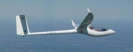
The SB-14 is a high performance glider of the 18-m class. I did the initial design of the wing structure, to be built from carbon fiber using wet-layup and vacuum bagging, using aeroelastic tailoring. The long, slender wing of a glider is particularly suitable to modify the elastic response of a wing by arranging the structure in a certain way. I wrote my own software (Fortran) to determine the influence of fiber angle in the laminate and placement of the spar on the loads the wings encounters when flying through a gust. In conventional designs, the bending of the wing under load may cause the wing to twist in a way that the angle of attack is increased, which in turn increases the lift and therefore the bending moment. To avoid this, the location of the shear center and the fiber angle can be optimized to decrease or even reverse this behavior.
Spin Investigation of High Performance Glider (1991)
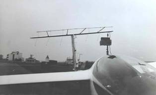
The aerodynamics of a spinning airplane are very complex and beyond methods of analysis. Therefore flight test was the only way to investigate the actual angles of attack and sideslip angles at the tail of a spinning glider. I modified an ASW-24 with a rack mounted in front of the vertical and the horizontal tail, to which wool tufts were attached. A camera mounted behind the cockpit was used to document the angles of the tufts during a spin. The results were used to predict spin characteristics and develop spin termination procedures for airplanes with different tail configurations.
Airfoil Design (1991 – present)

A lot of progress has been made to provide engineers with design tools for airfoil development. This allows engineers to tailor an airfoil exactly to its design requirements and to minimize its drag. I designed several series of airfoils, and used some of them on my motorglider Caro 1. Another examle was a low drag airfoil with an unslotted fowler flap for a glider project. The software allows the designer to modify either the geometry or the pressure distribution of an airfoil, and run performance analysis until the desired characteristics have been obtained. It permits investigation of more airfoil variations or design airfoils for a particular project, rather than having to select something from a catalog of old airfoils. A recent series of airfoils was designed for a canard airplane project.
Construction of the SB-13 Flying Wing (1986-87)

In 1986 I joined the Akademical Flying Group (Akaflieg) Braunschweig , which had just started to build the SB 13, a flying wing glider design. I participated in most of the construction of this unique 15 m (standard class) glider. The wings were all carbon fiber with high modulus carbon spars. It has two elevons per wing which shared the functions of elevator and aileron. The rudders were part of the winglets. It had the first all-aircraft parachute rescue system in a compartment aft of the cockpit. I flew the SB 13 and found it pleasant in smooth air but due to the low pitch damping and high aspect ratio swept wings, it was uncomfortable to fly in turbulence.
Selection of Aircraft Homebuilder Project support
Performance evaluation / flight test data reduction (BD-4, etc)
Engine cooling evaluations / improvements
Cassutt composite wing design
Loads and structural design for a DG2 (carbon F1 racer) wing
Pitts composite wings structural design
Development of a rotary engine installation
Engineering evaluation and repair instructions for wrecked Lancair Legacy
Horizontal tail modification Sportsman
Engine mount designs
Troubleshooting and solving a severe pitch oscillation problem in a Wheeler Express
Design (aerodynamic, loads, structure) of a composite wing for an LSA
Performance analysis, longitudinal and directional stability analysis of an inverted V-tail glider design
Structural design of a composite wing as a direct replacement for the Mooney M20A wood wing (same geometry)
Loads and structural analysis for a composite Spitfire replica
Conceptual design and loads for all metal VLA new airplane
Design of a steel tube fuselage structure for a motorglider using existing glider wings

